Ion Identity Molecular Networking (IIMN)
Introduction
The Ion Identity Molecular Networking (IIMN) workflow complements the Feature-Based Molecular Networking (FBMN) by grouping MS2 spectra not only through similarity of MS2 spectra, but also of MS2 spectra whose precursor ions fulfill the retention time, peak shape, user-defined parameters. It enables the visualization of patterns of ion species and brings together subnetwork from the same molecule to create an ion identity molecular family. IIN can be performed with MZmine, XCMS-CAMERA, or MS-DIAL.
You can find more information about IIN in this playlist and this video from an IIN Workshop.
Citations
This work builds on the efforts of our many colleagues, please cite their work:
For IIMN: Schmid R., Petras D., Nothias LF, et al. Ion Identity Molecular Networking for mass spectrometry-based metabolomics in the GNPS Environment. Nat. Comm. 12, 3832 (2021).
For FBMN: Nothias, L.-F., Petras, D., Schmid, R. et al. Feature-based molecular networking in the GNPS analysis environment. Nat. Methods 17, 905–908 (2020).
For GNPS: Wang, M., Carver J, Phelan V.V., et al. Sharing and community curation of mass spectrometry data with Global Natural Products Social Molecular Networking. Nat. Biotechnol. 34, 828–837 (2016).
And the tools you used to process your data.
Running the IIMN workflow
The Ion Identity Networking workflow is run throught the FBMN workflow by providing Supplementary Annotation/Pairs files in the "Advanced Extras" panel of the standard FBMN workflow interface.

Alternatively, the quickstart interface for FBMN can also be used:
![]()
Note that multiple Supplementary Pairs files can specified. Their content will be added.
Generating Supplementary Pairs
The Supplementary Annotations/Pairs files can be generated with the following software:
- MZmine: See the documentation
- XCMS-CAMERA: See the documentation
- MS-DIAL: See the documentation
Alternatively, the results of other software could be used as long as the LC-MS feature identifier (ID) matches the "SCANS=" number in the MGF file.
Supplementary pairs
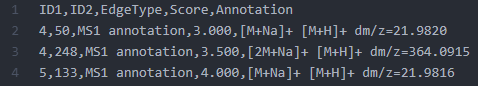
The Supplementary Pairs is a .CSV format file (coma separated), and must contains the following columns:
| Header | Description |
|---|---|
| ID1 | Node ID 1 matching the row IDs |
| ID2 | Node ID 2 matching the row IDs |
| EdgeType | Any string describing the type of edge |
| Score | A numerical value for the score (cannot be empty) |
| Annotation | A string annotation |
See an example of the Supplementary Pairs used in the Ion Identity Networking (IIN) workflow
IIMN networks with collapsed ion identity edges
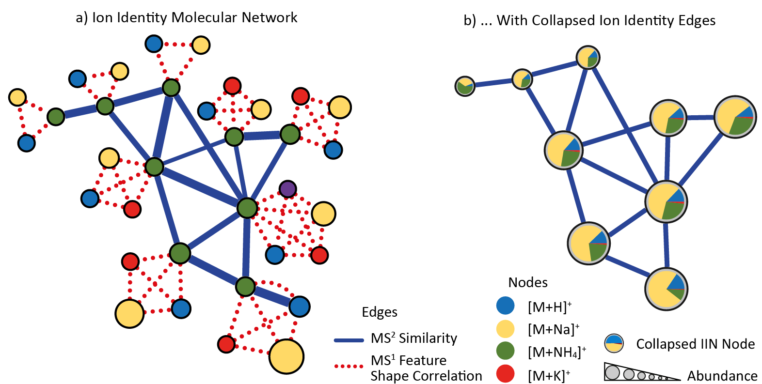
The IIMN workflow on GNPS generates two network types and provides downloads as graphml for downstream analysis and visualization. Both graphml networks are available in the "download cytoscape data" zip file provided on the job results page. The standard network contains MS² similarity edges from molecular networking combined with MS¹ ion identity networking edges (see a) in figure below). The alternative network b) collapses all ion identities that originate from the same neutral molecule (connected by red edges) into a single "molecular" node. The example below visualizes the relative ion abundances as pie charts on the collapsed nodes and uses the summed intensity for the node sizes. The collapsed nodes inherit the "shared name" of one of the removed ion identity child nodes. This node column can be used for a comparison between IIMN networks with or without collapsing or to compare them to FBMN networks.
Exploring the IIMN workflow in Cytoscape
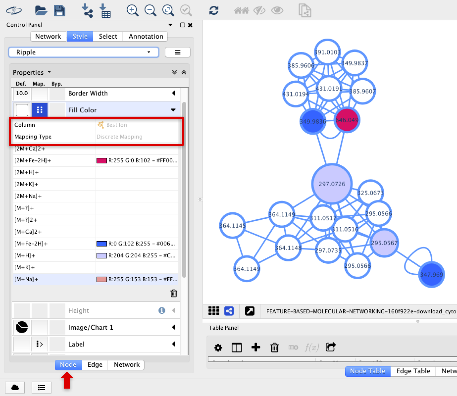
The additional edges that IIMN identified as adducts and in-source modifications are visualized in Cytoscape.
The different types of ions can be observed in different node colors if the Best Ion option is chosen in Fill Color, and Discrete Mapping type is selected.
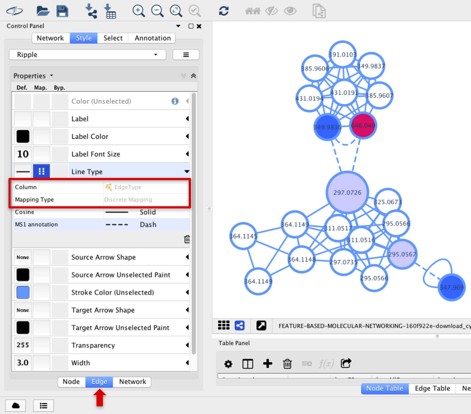
The lines connecting the nodes can be deferred if the connection represents a cosine or a MS1 annotation from INN. In the Line Type option, select EdgeType with Discrete Mapping.
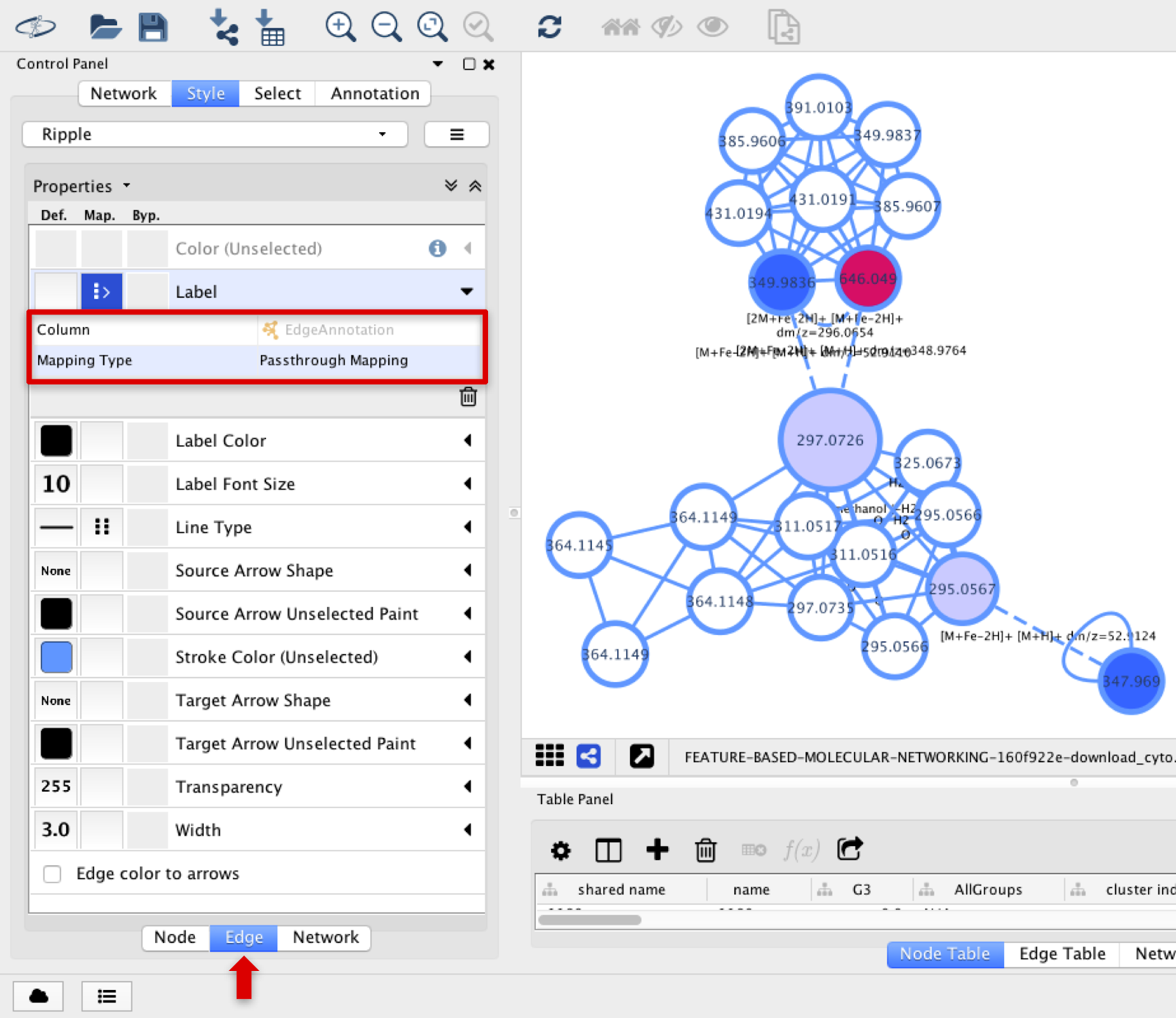
The annotation of the adducts or in-source fragmentations connected in the MS1 level can be annotated in the edges connecting the corresponding nodes. In the Label option, select Edge Annotation with Passthrough Mapping.
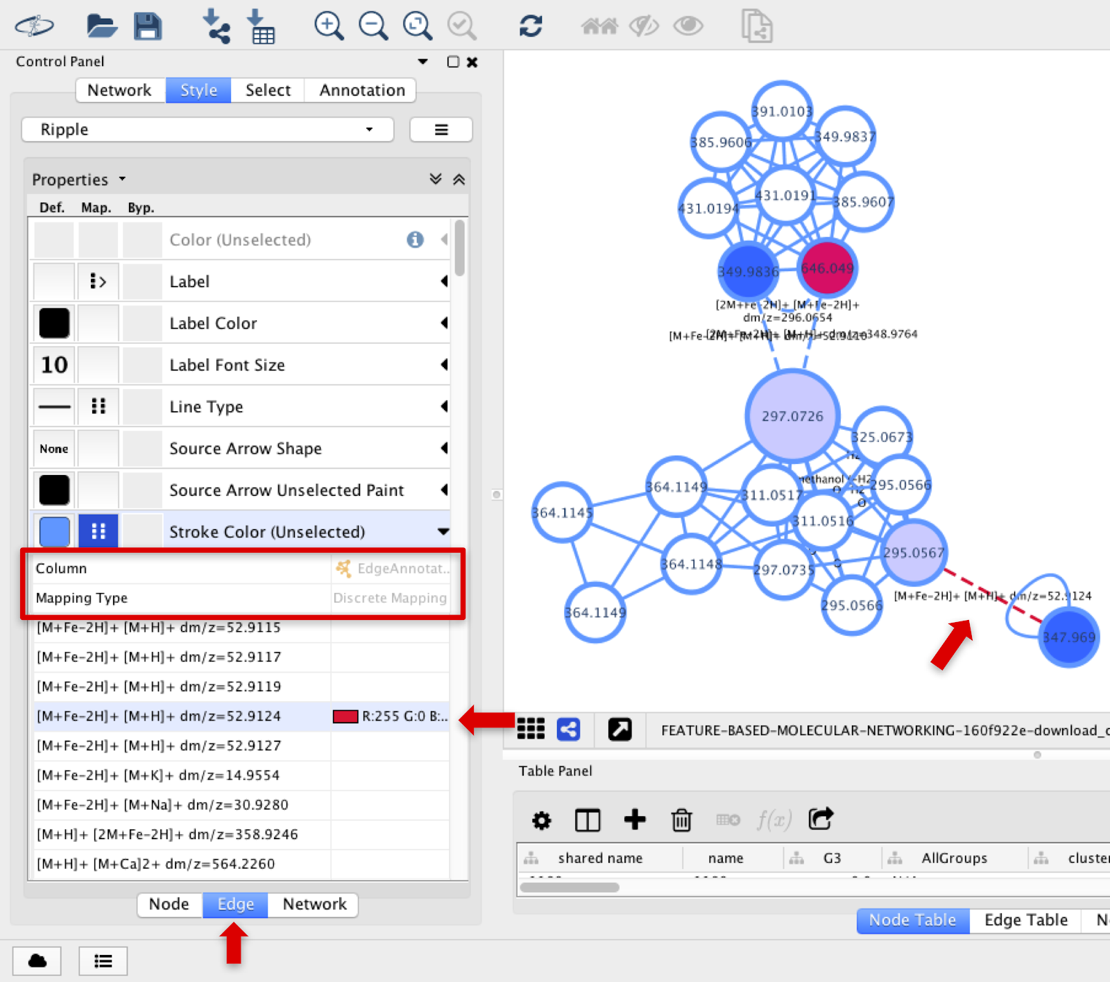
Specific types of adducts’ edges can be colored differently by selecting Stroke Color (Unselected) section, and choosing Edge Annotation and Discrete Mapping.
Page Contributions